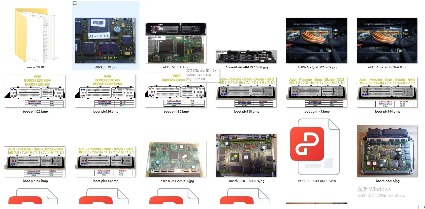
ECU Collection Pinout File Automotive ECU Pinout Connection For Ford/BMW/Toyota/Iveco Wiring Diagram ECU Map VS ALLDATA AUTODATA
29,74€ Original price was: 29,74€.11,04€Current price is: 11,04€.
ECU Collection Pinout File Automotive ECU Pinout Connection For Ford/BMW/Toyota/Iveco Wiring Diagram ECU Map VS ALLDATA AUTODATA
Dear customer,
1.Thank you for your attention, please read all the detailed descriptions of this product carefully, we have a very detailed explanation of this; if the transaction is abnormal due to your lack of reading, we will not be responsible for it.
2.If you purchased the ”Send by email or Send download link”, it means that you purchased the “download link”, Please send us your e-mail,we will send it to you through the e-mail, and randomly send you an irrelevant package, thank you for your understanding.
3.If you purchased the ”CD” or ”U-disk”, it means that we will definitely send the package to you, please copy all the files to your computer C drive after receiving the package, then start installing it
4.This software is a professional tool, please purchase carefully if you do not know how to use it. Once the software is sold, returns are not supported.
5.All our products come with installation videos and installation manuals
6.If you do not understand the above information, please come to consult us. Look forward to your order, Best wishes!
Huge Ecu Pinout Collection of ECU Pinout Files!
ECU Pinout offers a comprehensive collection of ECU pinout diagrams for various vehicle makes and models. You can search for specific ECUs or browse through the available categories. Some vehicle manufacturers provide official documentation, including ECU pinout diagrams, in their service manuals or technical resources.
What is a Pinout?
A pinout, also known as a wiring diagram or connector diagram, illustrates the connections and functions of the pins on an electronic device, such as an ECU. Pinouts are essential in diagnosing and troubleshooting electronic systems, as they provide valuable information on power supply, ground connections, sensor inputs, and output signals.
Understanding Pinout Diagrams
Pinout diagrams typically consist of tables with rows and columns, providing information on pin numbers, functions, voltage levels, and signal types. Let’s delve into each component of a pinout diagram:
Pin Number:
Each pin on the ECU has a unique number, facilitating easy identification and reference.
Function: This column describes the purpose or role of each pin, such as power supply, ground, sensor input, or output signal.
Voltage Levels: Pinout diagrams specify the voltage levels for power and ground pins, which is crucial for proper functioning of the ECU.
Signal Types:
These diagrams also indicate the types of signals transmitted through certain pins, such as analog, digital, or PWM (Pulse Width Modulation).
Benefits of Using Pinout Diagrams
Advantages when working with Bosch ECUs:
Easy Troubleshooting
Pinout diagrams simplify the process of identifying faulty connections or components, saving time and effort.
Accurate Diagnosis
By understanding the pin functions and voltage levels, technicians can accurately diagnose issues and make necessary repairs.
Efficient Tuning
Pinout diagrams aid in the tuning and modification of ECUs, ensuring optimal performance and compatibility with aftermarket components.
ECU Swapping
When replacing a damaged ECU, having access to the pinout diagram ensures the correct connections are made, preventing further damage or compatibility issues.


| Hign-concerned Chemical | None |
|---|---|
| Electronic | No |
| Is Batteries Included | No |
1 review for ECU Collection Pinout File Automotive ECU Pinout Connection For Ford/BMW/Toyota/Iveco Wiring Diagram ECU Map VS ALLDATA AUTODATA
Add a review Cancel reply
Related products
Softwares
DTC Remover 1.8.0.0 For DTC Remover 1.8.5.0 KESS KTAG FGTECH OBD2 ECU Chip Tuning Software Full MTX


Ч***ч –
Отличный продавец. Отправил сразу. Артур.